Innovation methods of a hollow rotary actuator
1.What is a hollow rotary actuator?
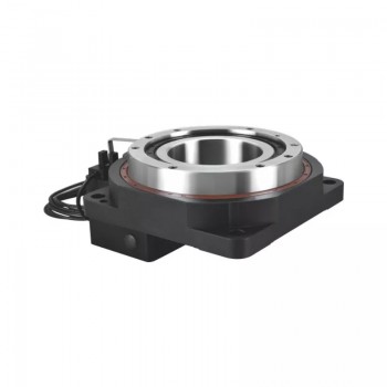
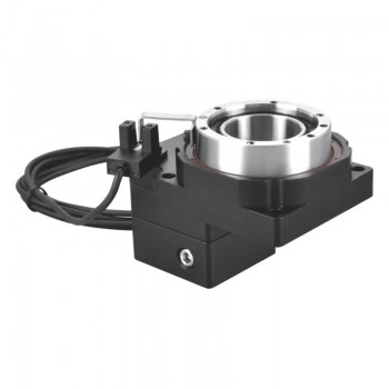
A hollow rotary actuator is an integrated electromechanical assembly that produces controlled rotational motion while providing a central through bore (a hollow shaft) that allows cables, pneumatic hoses, fluid lines, optical fibers, or even laser beams to pass axially through the device without interference. It typically combines a motor, a precision gear reducer, high capacity bearings, a position feedback encoder, and sometimes a fail safe brake ,all enclosed in a compact housing with the hollow bore running from one end to the other.
2.Main structure parts of hollow rotary actuator
1.Housing:The outer shell that encloses and protects all internal components, ensuring structural rigidity and mounting interface.
2.Cross Roller Bearing:The core load bearing component with 90° crossed rollers, supporting radial, axial loads and overturning moments while maintaining high rotational accuracy and stiffness.
3.Precision Gearbox:Reduces motor speed and increases torque; planetary gears offer high rigidity, while harmonic gears provide zero backlash precision.
4.Hollow Output Shaft/Table:The central rotating part with a through hole for cables, air tubes or shafts to pass through, avoiding winding during rotation.
5.Input Shaft and Flange:Transmits motor power to the gearbox; the flange enables rigid connection with servo/stepper motors.
6.Sensing Device (Encoder/Sensor):Provides real time position/speed feedback to the controller for precise closed loop positioning.
7.Seals:Prevent dust, contaminants and lubricant leakage, ensuring long term reliability of internal components.
3.Performance advantages of a hollow rotary actuator
1.Compact and Space Saving Design:These actuators feature a hollow shaft, which allows for routing cables, hoses, and other essential components through the center. This design not only minimizes the space required for installation but also reduces the complexity of the system, making them ideal for compact machinery or systems with limited available space.
2.High Torque and Load Capacity:Hollow rotary actuators are engineered to provide high torque outputs while maintaining a relatively small footprint. The unique construction of these actuators allows them to handle higher loads compared to traditional actuators.
3.Efficient Power Transmission:Due to their robust internal gearing and efficient mechanical design, hollow rotary actuators ensure effective power transmission with minimal loss. This results in better energy efficiency and overall system performance.
4.Improved Rotational Accuracy and Precision:The precise control capabilities of hollow rotary actuators make them an excellent choice for applications requiring high accuracy. These actuators can achieve fine, incremental rotations with exceptional repeatability.
5.Reduced Weight and Vibration:The hollow shaft design contributes to a reduction in the overall weight of the actuator. In applications like robotics and aerospace, where weight reduction is critical, hollow rotary actuators help optimize the system’s performance by reducing unnecessary mass.
6.Enhanced Durability and Longevity:Hollow rotary actuators are built to withstand harsh working environments. Their construction, often using high quality materials, allows them to operate in extreme temperatures, pressures, and under heavy loads. This makes them highly durable and capable of enduring long operational lifecycles, thus reducing the need for frequent maintenance and replacements.
7.Simplified Integration with Other Systems:The hollow center of the actuator allows for easy integration with other mechanical systems, such as fluid transfer systems, cables, and sensors. This versatility simplifies the design and integration process in complex machinery and robotic systems.
4.Innovation methods of a hollow rotary actuator
1.Advanced Material Selection:The continuous improvement of materials used in hollow rotary actuators has been a key driver of innovation. Advanced composites and high strength alloys are now being used to fabricate actuator components, which enhances their durability and resistance to wear, corrosion, and extreme environmental conditions.
2.Integration of Smart Technologies:The integration of smart technologies into hollow rotary actuators is a significant leap in actuator innovation. By incorporating sensors, IoT connectivity, and real time data analytics, these actuators can now provide real time feedback, predictive maintenance, and enhanced control.
3.Advanced Gear Design and Efficiency:The design of the internal gearing in hollow rotary actuators has seen considerable advancements in recent years. Researchers have developed more efficient gear systems, such as planetary gear configurations, which optimize torque transmission and reduce mechanical losses.
4.Modular and Customizable Designs:Modularity has become an important aspect of hollow rotary actuator innovation. Manufacturers are now designing actuators with modular components that can be easily customized based on the specific needs of the application.
5.Optimization of Sealing and Lubrication Systems:The optimization of sealing and lubrication technologies has played a significant role in enhancing the performance of hollow rotary actuators. The development of advanced seals ensures better protection against contaminants, moisture, and dust, leading to increased reliability in harsh environments.
6.Miniaturization for Compact Applications:With the rise of compact machinery and systems, miniaturization has become a major area of focus for hollow rotary actuators. Through the use of precision engineering and advanced manufacturing techniques, smaller actuators with high torque to size ratios are now possible.
7.Enhanced Control Algorithms and Precision:The development of advanced control algorithms is another innovation method that has enhanced the precision of hollow rotary actuators. New algorithms, often utilizing machine learning and AI, allow for better control over the actuator’s movement, ensuring smoother and more accurate positioning.
Source:https://www.stepperyoyo.com/2026/04/innovation-methods-of-hollow-rotary.html
Suitable applications of manual pulse generator
1.Basic knowledge about manual pulse generator
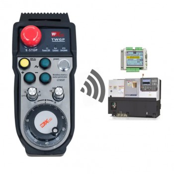
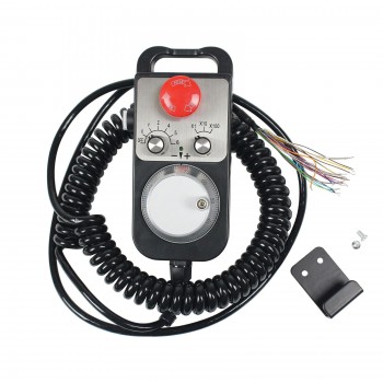
A manual pulse generator, also commonly known as an electronic handwheel, is a manual input device used to control the motion of CNC machine tools, robots, and other automated positioning systems. It generates a stream of electrical pulses proportional to the rotation of a handwheel, allowing the operator to jog, position, or fine tune axes with high precision.Unlike a simple rotary encoder, an MPG is designed for human operation. It provides an intuitive, tactile way to move a machine axis incrementally or continuously, making it essential for setup, tool alignment, and manual machining.
2.Types of manual pulse generators
1.Optical MPG:Uses a glass or plastic code disc with slits and a photodiode sensor. High resolution, excellent accuracy, but sensitive to dust and oil. Common in clean workshops.
2.Magnetic MPG:Uses a magnetised wheel and Hall sensors. Lower resolution but robust against contamination. Ideal for harsh machining environments.
3.Incremental MPG:Outputs A or B quadrature pulses. Does not retain position after power loss. Most common and cost effective.
4.Absolute MPG:Outputs a unique digital code for each position. Retains position information, but more expensive and rarely needed for manual control.
5.Panel mount MPG:Designed to be fixed to a machine control panel. Smaller handwheel, no cable, wired directly inside the cabinet.
6.Portable MPG:Hand held unit with a long cable, often with magnetic base or hook. Allows operator to stand near the workpiece while controlling the machine.
3.Common functions of manual pulse generator
1.Incremental jog control with high resolution:The core function of an MPG is to convert the mechanical rotation of a handwheel into electrical pulse signals. Each pulse corresponds to a fixed movement increment of a machine axis. This enables operators to perform extremely fine positioning, often at micrometer or even sub micrometer levels, which is essential for precision machining and alignment tasks.
2.Multi axis selection capability:Most MPGs are equipped with an axis selection switch, allowing users to control different machine axes using a single device. This reduces hardware complexity and provides a centralized manual control interface, especially in multi axis CNC or robotic systems.
3.Selectable movement resolution:MPGs typically include a scaling or multiplier selector. This function determines how much the machine moves per pulse generated. A lower scale is used for fine adjustments, while higher scales allow faster positioning over longer distances.
4.Bidirectional motion control:The MPG detects the direction of handwheel rotation and translates it into corresponding forward or reverse movement of the selected axis. This intuitive control mechanism allows operators to adjust positions naturally without needing additional directional commands.
5.Real time feed rate control:The speed at which the handwheel is turned directly affects the frequency of generated pulses. As a result, the machine's movement speed changes in real time based on operator input. This provides a highly responsive and proportional control experience, which is particularly useful during delicate adjustments.
6.Manual override and intervention:MPGs allow operators to temporarily override automated or pre programmed operations. This is critical during setup, troubleshooting, or unexpected situations where manual intervention is required to prevent errors or damage.
7.Precision alignment and calibration support:In applications such as tool setting, probe alignment, or optical positioning, MPGs enable fine tuned adjustments with immediate feedback. This function ensures that components are accurately aligned, improving overall system performance and measurement reliability.
4.Suitable applications of manual pulse generator
1.CNC machine tool operation:Manual pulse generators are widely used in CNC machines to control axis movement manually. Operators can precisely move the cutting tool or workpiece in small increments, which is essential for setup, alignment, and fine adjustments during machining processes.
2.Precision positioning systems:In systems requiring accurate positioning, such as linear stages or rotary tables, MPGs allow operators to input incremental movements with high control. This is particularly useful in calibration and alignment tasks where automated control may not provide sufficient flexibility.
3.Robotics teaching and debugging:During robot programming and maintenance, MPGs enable manual jogging of robot joints or end effectors. Engineers can safely and precisely position the robot for teaching points, testing movements, and troubleshooting without relying solely on pre-programmed paths.
4.Industrial automation panels:MPGs are commonly integrated into control panels for automated equipment. They provide a simple and reliable interface for manual overrides, allowing operators to intervene in automated processes for inspection, adjustment, or emergency handling.
5.Laser cutting and engraving machines:In laser systems, precise positioning of the laser head is critical. MPGs allow operators to fine tune the position before starting a job, ensuring accuracy and reducing material waste.
6.3D printing and additive manufacturing:MPGs can be used in advanced or industrial 3D printers to manually control the movement of print heads or build platforms. This is useful for calibration, bed leveling, and maintenance operations.
7.Testing and measurement equipment:In laboratories and metrology applications, MPGs facilitate controlled incremental movement of sensors, probes, or samples. This ensures accurate data collection and repeatable experimental conditions.
8.Packaging and assembly lines:In manufacturing environments, MPGs allow operators to manually adjust machine positions during setup or when handling irregular products. This improves flexibility and reduces downtime during changeovers.
Source:https://www.stepperyoyo.com/2026/04/suitable-applications-of-manual-pulse.html
How to maintain stable operation of ATC spindle motor?
1.Core definitions of ATC spindle motor
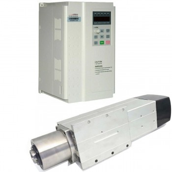
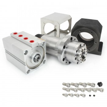
An ATC spindle motor is a high-precision integrated component designed for CNC machining centers, which integrates a high-speed motor, a precision spindle, an automatic tool change mechanism, and a tool clamping system. It is responsible for driving the cutting tool to rotate at high speed to complete machining operations such as milling, drilling, and tapping, and can automatically switch between different tools according to the machining program without manual intervention. ATC spindle motors achieve continuous and efficient machining by reducing tool change time and eliminating human errors in tool change.
2.Working steps of ATC spindle motor
1.Spindle orientation: The spindle decelerates and stops at a specific preset angular position. This ensures that the orientation key of the tool holder aligns perfectly with the tool changer mechanism.
2.Move to tool change position: The machine's axes move the spindle to a designated "tool change position" where it can interact with the tool magazine or gripper arm.
3.Tool unclamping: A pneumatic solenoid activates a piston inside the spindle. This pushes a drawbar down, which compresses disc springs to open the internal collet and release the current tool holder.
4.Air blast cleaning: Simultaneously with the tool release, a blast of compressed air is shot through the spindle nose to clean dust and debris from the taper. This ensures a clean and accurate fit for the next tool.
5.Tool exchange:In arm-type systems, a gripper arm grabs both the old tool in the spindle and the new tool in the magazine, rotates, and swaps them.In arm-less systems, the spindle moves directly to the tool rack to drop off the old tool and pick up a new one.
6.Tool clamping: Once the new tool is seated in the spindle taper, the solenoid valve releases the air pressure. The internal disc springs pull the drawbar back up, securely clamping the tool holder in place with high force.
7.Verification: Built-in sensors confirm the state of the "drawbar closed" or "tool present" signals to the CNC controller.
8.Resuming operation: The axes move back to the machining area, and the spindle accelerates to the programmed speed for the next operation.
3.The importance of ATC spindle motor
1.Increased productivity:With an ATC spindle motor, the machine can automatically switch between different cutting tools without requiring manual intervention. This results in a significant increase in productivity and a reduction in downtime, as the machine can continue to operate without interruption.
2.Improved accuracy:ATC spindle motors are designed to provide precise control over the cutting tool, resulting in improved accuracy and repeatability. The ability to change tools automatically also reduces the risk of errors that can occur when changing tools manually.
3.Versatility:ATC spindle motors can accommodate a wide range of cutting tools, allowing for greater versatility in the types of operations that can be performed. This makes them ideal for applications that require a variety of cutting tools and machining processes.
4.Reduced operator fatigue:Since the ATC spindle motor automates the tool-changing process, the operator can focus on other tasks, reducing the risk of fatigue and improving safety.
5.Time-saving:The automatic tool change function saves time by eliminating the need for the operator to manually change the tool. This results in faster machining times and increased throughput.
4.Practical methods to maintain stable operation of ATC spindle motor
1.Cooling system check: For water-cooled ATC spindles, verify that the coolant level is sufficient, the filter is clean, and the pipeline is free of blockages; set the coolant temperature to 20–25°C. For air-cooled spindles, ensure the cooling fins are free of dust, debris, or oil stains, and that the cooling fan operates normally to guarantee smooth air circulation.
2.Lubrication system verification: Confirm that the lubricant level meets the standard, and that the lubrication pipeline is unobstructed and free of leaks. For oil-air lubrication systems, check the oil mist concentration and air pressure to ensure uniform lubrication of bearings and moving parts.
3.Spindle taper and tool clamping check: Use clean compressed air to blow out metal chips, coolant residue, and dust from the spindle taper hole and collet—contamination here can cause tool runout and clamping instability. Inspect the taper surface for scratches, rust, or wear; if any damage is found, polish it with fine sandpaper or replace the collet.
4.Electrical and control system check: Turn on the CNC system and ATC control module, check for error codes on the control panel, and ensure normal communication between the spindle motor and the CNC system.
5.Temperature monitoring: Use an infrared thermometer to measure the spindle surface temperature regularly; the normal operating temperature should not exceed 70°C. If the temperature rises above 80°C, stop the machine immediately to cool down, as overheating can damage bearings, warp the spindle shaft, and degrade lubrication performance.
6.Noise and vibration detection: Listen for abnormal sounds, which may indicate bearing wear, tool imbalance, or spindle misalignment. Use a vibration meter to measure the vibration amplitude— the standard value should be ≤2.5mm/s; excessive vibration will affect machining precision and accelerate component wear.
7.Tool change stability check: Observe the automatic tool change process to ensure there is no jamming, tool dropping, or positioning deviation. If the tool change fails or the positioning error exceeds ±0.005mm, stop the machine to troubleshoot immediately, as repeated tool change failures can damage the manipulator and spindle taper.
Source:https://www.stepperyoyo.com/2026/04/how-to-maintain-stable-operation-of-atc.html
Stepper Motor Sizing and NEMA Standards List
Stepper motors are frequently identified by their NEMA frame designation, such as NEMA6, NEMA8, NEMA11, NEMA 14, NEMA 17, NEMA 23, Nema 34 or NEMA 42. The NEMA number refers primarily to the mechanical interface of the motor, particularly the mounting face dimensions. It does not define torque capability, electrical characteristics, or winding configuration.
For this reason, frame size should be treated as a mechanical reference rather than a complete description of motor performance. Motors with the same NEMA frame designation may differ in body length, shaft geometry, winding parameters, rotor inertia, and rated current.
Understanding what the NEMA designation does—and does not—define is the starting point for selecting a stepper motor for a motion system.
NEMA Frame Definition: Mechanical Interface
The NEMA frame designation corresponds approximately to the mounting face dimension expressed in tenths of an inch.
Examples include:
NEMA 6: approximately 0.6 inches (about 15 mm)
NEMA 8: approximately 0.8 inches (about 20 mm)
NEMA 11: approximately 1.1 inches (about 28 mm)
NEMA 14: approximately 1.4 inches (about 36 mm)
NEMA 16: approximately 1.6 inches (about 41 mm)
NEMA 17: approximately 1.7 inches (about 42 mm)
NEMA 23: approximately 2.3 inches (about 56 mm)
NEMA 24: approximately 2.4 inches (about 60 mm)
NEMA 34: approximately 3.4 inches (about 85 mm)
NEMA 42: approximately 4.2 inches (about 106 mm);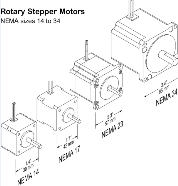
The standard primarily describes the physical interface used to mount the motor. Depending on the manufacturer and the specific product series, the frame standard typically relates to:
Mounting face dimensions
Bolt hole spacing and diameter
Pilot or centering boss
Shaft diameter
Shaft extension length
These dimensions help determine whether the motor will physically fit within a machine assembly. However, the NEMA designation alone does not ensure that two motors from different manufacturers will be identical in every mechanical detail. Shaft features, connector orientation, body length, and tolerance limits may vary.
NEMA 14 Stepper Motor: Compact Mechanical Envelope
A NEMA 14 stepper motor has a mounting face close to 1.4 inches square. This frame size appears in motion systems where available installation space is limited and the machine structure is designed for a smaller mechanical envelope.
Within the NEMA 14 family, motors may still differ in several parameters, including:
Body length
Holding torque
Rotor inertia
Winding resistance
Current rating
Inductance
Shaft configuration
The frame size establishes the mounting interface. The remaining parameters determine how the motor behaves once connected to a drive and load.
NEMA 17 Stepper Motor: Common Mechanical Interface
A NEMA 17 motor has a mounting face of roughly 1.7 inches. In many product families, this frame size is available in several body lengths. The mounting face remains unchanged while the motor body becomes longer or shorter depending on the internal magnetic structure.
Changes in body length are usually associated with variations in the internal magnetic stack and rotor assembly. These differences influence several operating parameters, including torque capability, rotor inertia, and winding characteristics.
Because of this variation, replacing one NEMA 17 motor with another may require confirmation of electrical ratings and driver settings, even if the mounting interface is identical.
NEMA 23 Stepper Motor: Mechanical Frame Description
A NEMA 23 stepper motor has a mounting face of approximately 2.3 inches. This frame size is used in motion systems where the mechanical layout accommodates a larger motor envelope.
As with smaller frame sizes, motors within the NEMA 23 category are available in multiple body lengths and winding configurations. The mechanical frame size defines the mounting pattern, but the electrical behavior depends on the motor design.
When selecting a motor in this frame category, the following factors are usually evaluated:
Load torque
Reflected inertia
Required acceleration
Operating speed range
Drive voltage
Current limits of the motor driver
Thermal limits of the motor
These factors determine whether the selected motor can operate within the required motion profile.
NEMA 34 Stepper Motor: Large Frame Size
A NEMA 34 stepper motor has a mounting face close to 3.4 inches. Motors in this frame category occupy a larger mechanical footprint and are commonly integrated into machine assemblies designed for higher load capacity or different inertia conditions.
As with other frame sizes, NEMA 34 motors are available with different body lengths and winding specifications. Two motors with the same NEMA 34 mounting face may have different electrical ratings or rotor inertia values.
Mechanical integration becomes more significant at this scale. Shaft coupling, mounting stiffness, and load transmission components should be considered as part of the overall system design.
Motor Body Length and Stack Design: Internal Structure
Within a single NEMA frame series, body length is one of the primary variables used to create multiple motor variants.
Increasing the active magnetic length of the motor changes several internal parameters, including:
Magnetic interaction within the stator and rotor
Rotor inertia
Winding inductance
Thermal mass of the motor body
These parameters influence the behavior of the motor when driven by a motion controller and driver. Motor selection therefore involves both mechanical and electrical considerations.
Frame Size and Motor Selection: Different Decisions
Selecting a NEMA frame determines whether the motor fits within the available mechanical space. Motor sizing determines whether the motion system can perform the required movement.
Motor sizing typically considers:
Load torque requirements
Acceleration and deceleration profile
Reflected inertia from mechanical transmission
Target operating speed
Driver current capability
Available supply voltage
Thermal conditions of the installation
Frame size addresses mechanical packaging. Motor sizing addresses motion capability.
Interchangeability Check: Mechanical and Electrical Parameters
Motors with the same NEMA frame designation may share the same mounting interface, but full interchangeability requires verification of both mechanical and electrical details.
Before replacing one motor with another, confirm:
Mounting face dimensions
Bolt hole pattern
Pilot diameter
Shaft diameter and shaft length
Shaft key, flat, or other shaft feature
Body length
Lead exit or connector orientation
Rated current
Winding resistance and inductance
Driver compatibility
Reviewing these items helps prevent mechanical mismatch and electrical configuration errors.
Engineering Summary
NEMA frame numbers identify the mechanical mounting interface of a stepper motor. They do not define the torque capability, electrical characteristics, or operating limits of the motor.
Within each frame size, motors may differ in body length, winding parameters, rotor inertia, and electrical ratings. Final motor selection therefore depends on both the mechanical constraints of the machine and the electrical and dynamic requirements of the motion system.
Sizing evaluates the motor, driver, load, and motion profile as a single system rather than as isolated components.
Source:https://www.oyostepper.com/article-1074-Stepper-Motor-Sizing-and-NEMA-Standards-List.html
The Application of servo motor and how it works
A servo motor is an electric actuator that operates as part of a closed-loop system. It includes a feedback mechanism—typically a sensor such as an encoder—that continuously reports the motor's actual position or speed to a controller. This allows the system to adjust its output until the desired state is reached.
When a command is sent, an electrical signal moves the output shaft to a specified angle, position, or velocity. The feedback device confirms whether the target has been achieved, and corrections are applied as needed.
Servo motors operate within a closed-loop system, meaning position and speed are continuously monitored and adjusted. In contrast, open-loop systems execute commands without verifying the final position.
A typical servo motor consists of a standard DC or AC motor combined with a feedback sensor and a control circuit. The control circuit interprets input signals and drives the motor accordingly..png)
Types of Servo Motors
Servo motors are available in several configurations, each suited to different types of movement. Three common types include:
Continuous rotation servos are designed to spin continuously in either direction. Speed can be controlled, but position cannot. Hobbyist projects—small robots, toy cars, or RC vehicles—often rely on these motors for drive systems.
Positional rotation servos move to and hold a specific angular position, typically within a range of 0 to 180 degrees. They are used in radio-controlled models, robotic arms, and other applications where angular positioning is required.
Linear servos produce motion along a straight line rather than rotating. They are found in applications requiring precise linear movement, such as industrial automation or actuation systems.
Beyond configuration, servo motors also differ in their power source, which affects where and how they are used.
AC and DC Servo Motors
Servo motors may be powered by either alternating current (AC) or direct current (DC). The choice between the two depends on the application requirements.
AC servo motors are commonly used in industrial equipment such as machine tools, robotics, and automation systems. They are designed to handle higher voltages and are typically found in applications requiring continuous operation. Voltage changes are managed through external transformers or drives.
DC servo motors are often used in smaller systems where rapid response and straightforward control are needed. Current flow is unidirectional, and control is typically achieved by varying the voltage applied to the motor windings. These motors appear frequently in battery-powered devices, hobbyist projects, and small-scale automation.
Applications of Servo Motors
Servo motors appear in various industrial and consumer applications. In manufacturing, they control axis movement in machine tools and CNC equipment. Factory automation systems—conveyors, pick-and-place units, and assembly lines—also rely on them for motion control.
Material handling and packaging machinery represent another major use case. Robotics, both industrial and hobbyist, depends on servo motors for joint movement and positioning. Radio-controlled models use them to control surfaces or steering in airplanes, cars, and boats.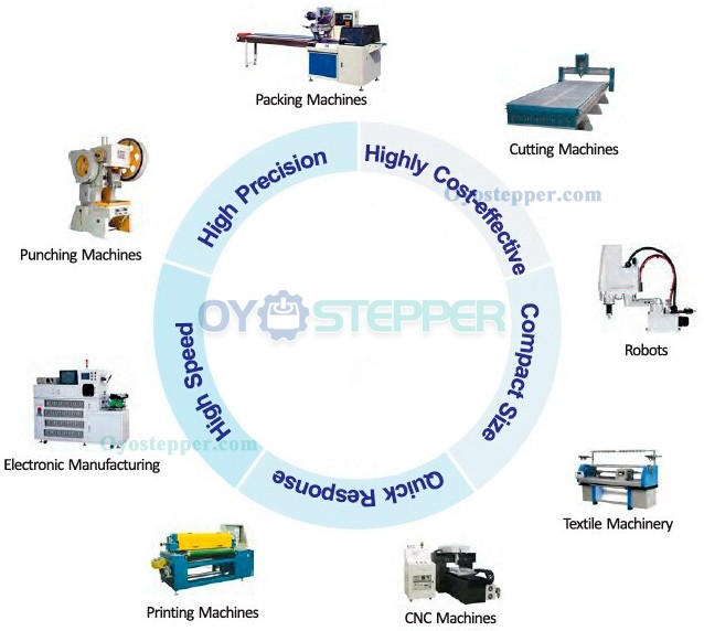
Other applications include:
Aerospace systems, where they regulate hydraulic valves and actuators
Automotive systems, such as cruise control actuators and throttle control
Consumer electronics, including DVD and Blu-ray players, where they open and close disc trays
Toys and educational kits that require controlled motion
In each of these applications, the servo motor operates within its rated specifications. Acceleration, speed, and torque are determined by the motor design and the drive system used.
Operational Characteristics
Servo drives regulate motor speed, position, and acceleration through closed-loop control. When energized, the motor can maintain a set position. Acceleration and deceleration rates are defined by the motor's specifications and the capabilities of the connected drive.
Machines and robots equipped with servo motors are capable of controlled motion across a range of operating conditions. Their performance is influenced by factors such as load, speed, and duty cycle—all of which are outlined in manufacturer documentation.
Servo motors are available with different cost structures and maintenance intervals depending on the model and application. They can be integrated into systems that support standard control interfaces, provided that voltage, current, and signal requirements are met.
Source:https://www.oyostepper.com/article-1117-The-Application-of-servo-motor-and-how-it-works.html
Main advantages and applications of hybrid stepper motor
1. Basic introduction to hybrid stepper motor
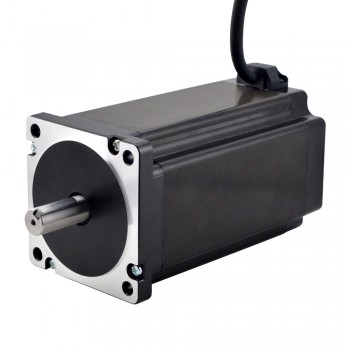
A hybrid stepper motor is a type of electric motor that combines the features of both permanent magnet and variable reluctance stepper motors, offering higher torque and precision than either type alone. It achieves this by having a rotor with permanent magnets and a stator with electromagnets, which interact to create precise rotational movement in discrete steps when energized by electrical pulses.
2. Working principle of hybrid stepper motor
Hybrid stepper motors operate by precisely controlling the energization of stator windings to rotate the rotor in discrete steps. This is achieved by creating a magnetic field that interacts with the permanent magnets embedded in the rotor, causing it to move in alignment with the field's direction. The step angle, or the amount of rotation per step, is determined by the motor's design, including the number of rotor teeth and stator poles.
3.Advantages of hybrid stepper motor
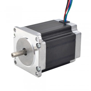
1. High Positional Accuracy and Precision:One of the most significant advantages of hybrid stepper motors is their exceptional positional accuracy and precision. These motors can move in very small increments, typically 1.8 degrees per step. With precise control of each step, hybrid stepper motors provide highly accurate positioning, making them ideal for applications requiring precise movements, such as 3D printers, CNC machines, and medical equipment.
2. High Torque at Low Speeds:Another advantage of hybrid stepper motors is their ability to provide high torque even at low speeds. This characteristic is particularly useful in applications where the motor needs to start and move heavy loads, such as in industrial automation and robotics.
3. Open-loop Control:Hybrid stepper motors operate in open-loop control systems, which means they do not require feedback sensors to determine the rotor position accurately. This feature simplifies the control process and reduces system complexity. Open-loop control also eliminates the need for additional sensors, making the overall system more cost-effective.
4. Compact Size and High Power Density:Hybrid stepper motors are known for their compact size and high power density. The compact design makes them suitable for applications with limited space, such as small-scale automation systems and portable devices. Despite their small size, hybrid stepper motors can deliver mechanical power comparable to larger motors, thanks to their high power density.
5. Cost-effective Solution:Hybrid stepper motors offer a cost-effective solution compared to other motor types, such as servo motors. They have a relatively lower price point, making them more accessible for many applications. Additionally, the absence of feedback sensors further reduces the overall cost of the system.
4.Main applications of hybrid stepper motor
1.Robotics and Automation:Hybrid stepper motors are commonly used in robotics and automation due to their ability to provide precise and reliable motion control. These motors are essential for controlling the movement of robotic arms, grippers, and other automated systems. With their high torque output and accurate positioning capabilities, hybrid stepper motors play a crucial role in ensuring the smooth and efficient operation of robotic applications.
2.3D Printing and Additive Manufacturing:The use of hybrid stepper motors in 3D printing and additive manufacturing has revolutionized the way objects are produced. These motors are used to precisely control the movement of the print head and build platform, enabling highly accurate and intricate 3D printed designs. Hybrid stepper motors are favored in 3D printing for their ability to provide high-resolution and smooth motion, resulting in superior print quality.
3.CNC Machining and Milling:In CNC (Computer Numerical Control) machining and milling, hybrid stepper motors are widely used to drive the movement of cutting tools and workpieces with exceptional precision. These motors are capable of providing the high torque required for heavy-duty machining operations, while also delivering the accuracy needed for intricate and complex part production.
4.Medical Devices and Imaging Systems:Hybrid stepper motors play a critical role in medical devices and imaging systems, where precision and reliability are paramount. These motors are commonly employed in applications such as MRI machines, CT scanners, robotic surgery systems, and laboratory automation equipment. With their ability to deliver consistent and controlled motion, hybrid stepper motors contribute to the advancement of medical technology by enabling more accurate diagnostics, minimally invasive procedures, and improved patient care.
5.Automotive Systems and Electric Vehicles:In the automotive industry, hybrid stepper motors are utilized in a wide range of applications, including fuel injection systems, HVAC (heating, ventilation, and air conditioning) actuators, power seats, and electric power steering. With the shift towards electric and hybrid vehicles, the demand for hybrid stepper motors continues to rise as they are essential for controlling various vehicle components with precision and efficiency.
Source:https://www.steppernews.com/2025/07/main-advantages-and-applications-of.html
What are the selection criteria for CNC spindle motors?
1. Definition and function of CNC spindle motors
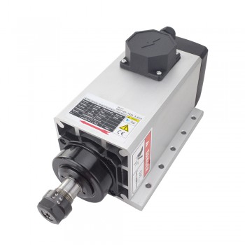
CNC spindle motors are one of the core power sources of CNC machine tools. Their main function is to provide cutting power for processing and realize the speed regulation and forward and reverse rotation of the spindle. The motor built into the spindle structure eliminates the mechanical loss of traditional belt/gear transmission, and the speed can reach tens of thousands of revolutions per minute, which significantly improves the processing efficiency and precision.
2. Working principle of CNC spindle motors
The working principle of CNC spindle motors is based on the generation of electromagnetic induction and rotational torque. It is integrated through AC high-frequency motors, and the motor is directly built into the spindle, which reduces the driving process, has a more compact structure, lower noise, higher mechanical efficiency, better precision, and smaller vibration amplitude. In addition, the spindle motor usually uses a photoelectric encoder to detect the speed and rotor position, and the detection signal is used as a feedback signal for vector frequency conversion control for magnetic field oriented control.
3. Advantages of CNC spindle motors
1. Compact structure: CNC spindle motors integrate the motor directly into the spindle, eliminating the transmission components such as belts and gears required by traditional spindles, thereby simplifying the structure and reducing space occupancy. This design integrates the motor and the spindle, further improving the compactness of the overall structure.
2. High speed: CNC spindle motors eliminate the mechanical loss and inertia limitations of the intermediate transmission link, and the speed can reach tens of thousands of revolutions per minute, which is significantly higher than traditional spindles (usually thousands of revolutions per minute).
3. High precision: Direct drive reduces transmission errors, and through precision bearings or magnetic suspension technology, it can effectively control thermal deformation and vibration, thereby improving processing accuracy.
4. Fast dynamic response: The integrated design of the motor and the spindle makes the inertia small, the acceleration and deceleration time short, and can respond quickly to CNC instructions, improving the flexibility and processing efficiency of the machine tool.
5. High power density: Modern CNC spindle motors usually require active cooling, such as water cooling or air cooling systems, to keep the spindle temperature stable, extend service life and improve processing quality.
6. Advanced technology: CNC spindle motors are driven by synchronous motors or asynchronous motors. Asynchronous motors are standard due to their high reliability and ease of use, while synchronous motors use permanent magnet technology, which is more efficient and generates less heat.
4. Selection requirements for CNC spindle motors
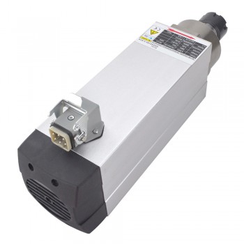
1. Power and torque: The spindle motor needs to have sufficient power and torque to cope with the cutting resistance requirements during rough machining. Motors with different center heights have different power and torque output capabilities. Motors with larger center heights are suitable for heavy-load start-up and operation occasions, while motors with smaller center heights are suitable for light-load, high-speed applications.
2. Speed range: The spindle motor needs to have a wide speed range, usually between 1000-15000rpm, to cover different process requirements such as drilling and fine milling. During the design phase of CNC machine tools, the technical indicators such as the output power and speed range of the spindle must be clearly defined to ensure that the spindle will not "stuck" due to insufficient power during cutting.
3. Dynamic response: The spindle motor needs to have fast dynamic response capabilities to ensure the smooth transition process. The dynamic response of vector control ensures that the transition process (Δv)/(Δt) is large enough to ensure the stability and accuracy of the processing process.
4. Servo characteristics: The spindle motor should have servo characteristics to achieve precise positioning and synchronization of the spindle, such as complex operations such as thread processing. The accuracy and stability of the servo system have a direct impact on the processing quality.
5. Vibration and thermal drift: The vibration value of the spindle motor should comply with ISO standards, and the vibration value is usually required to be less than 2.5mm/s. At the same time, it is necessary to have a thermal drift compensation function to ensure processing accuracy and stability.
6. Cooling system: The spindle motor should adopt an efficient cooling system, such as a heat pipe cooling system, to ensure that it can still maintain a good working condition under long-term operation or high temperature environment.
7. Magnetic circuit design: The magnetic circuit design of the motor should be optimized to reduce heat and improve efficiency. For example, the use of a unique additional magnetic pole design can reduce losses and improve motor efficiency.
